Friday, July 30, 2010

Week 15 The final update.

We have made some changes to our designs.During the fabrication on last week , we found out that our mechanism is too small compared to the others.Lucky we still had enough material to make a bigger mechanism.The designs remained the same , only the size was increased.

This is the updated Auto Cad drawings for our mechanism.As you can see , the length and width are much longer.

FULL:


Mechanism Plate:


Protuding Part:


Arm:


The fabrication of the new mechanism has taken place.


Cutting and drilling took place during lesson time on the 27th July.


As you can see the new mechanism is now 1.5x bigger than the first.This is to ensure that the claw is able to grab the can.


This is the end product after cutting and drilling parts of the mechanism.


We attached the servo horn to the claws by use a screw and a nut.This ensures that the two parts are held in place.


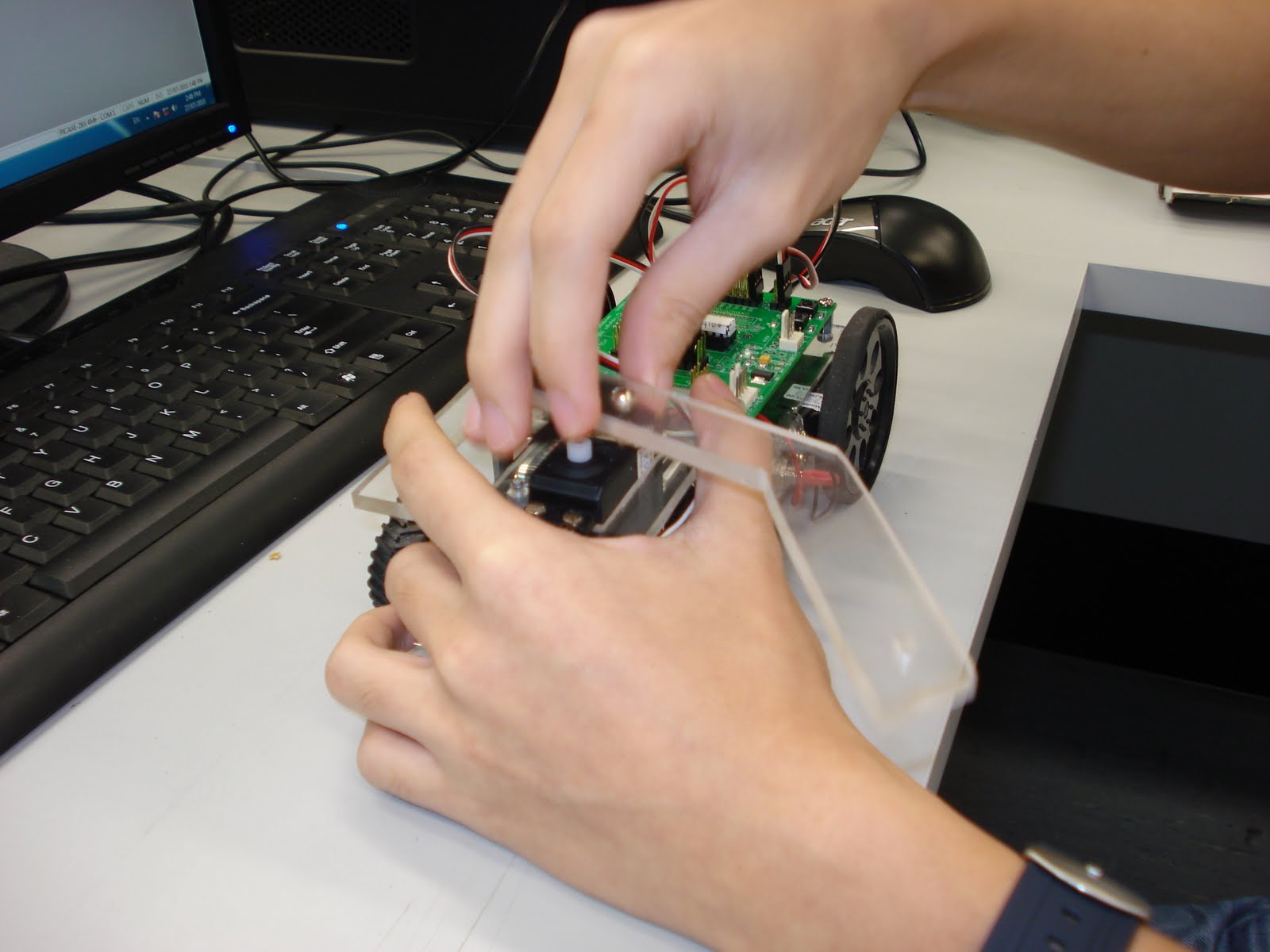
On Wednesday the 28th , testing of the mechanism took place. One part of the mechanism was used to determined the direction and the speed of the mechanism.We programmed it so that the claw would not crush the can.

We had some trouble with the programming as we need to program two servo motors.The left and right parts of the claw was suppose to rotate in an opposite direction.But it happen to go in the same direction.After a few adjustments we managed to program it with the right speed and the right direction.

Wednesday, July 21, 2010

AUTOCAD 2D DRAWING- updated again

Overall:


Part 1: Mechanism Plate


Part 2: Protuding Part


Part 3: Arm

Tuesday, July 20, 2010

Week 14 (Fabrication)

Full view:


1st piece of the mechanism: Mechanism Plate

2nd piece of the mechanism :Protuding part

3rd piece of the mechanism: The arm

Thursday, July 15, 2010

Week 13 AutoCad (Updated) and Planning

Deleted some unnecessary dimensions , components now have a separate border :
Full View:

Left View:

Middle View:

Right View:


These dimensions have been confirmed.
Planning of components on the polycarbonate plate is in progress.


Cutting of the plate will take place on 20/7/2010.

Tuesday, July 13, 2010

AUTOCAD 2D DRAWING (MODIFIED)

Modified the dimensions of the arm and separated each part into individual borders.
This is how it looks like:

Part 1:


Part 2:


Part 3:

Monday, July 12, 2010

AUTOCAD 2D DRAWING

THIS IS THE AUTOCAD 2D DRAWING.


Before:


Updated version:


THE PARTS INCLUDE:
1)Both of the arms(Plan view)
2)3rd angle projection of the right arm
3)3rd angle projection of the protruding part
4)Mechanism Plate

*Modified:
Polycarbonate plate with individual parts from 2) to 4) inside its border.
Where to place them is not finalized and will be done on 13/7/2010. The fabrication of individual parts will also be done on the same day.

Wednesday, July 7, 2010

Isometric drawing


This is the updated version of the isometric drawing which includes the mechanism, mechanism plate ans servo motors.

The servo motors powering the arm is non continuous.

Tuesday, July 6, 2010

IE drawing

The new IE drawing will be emailed instead of megaupload.
1)Both of the arms(Plan view)
2)3rd angle projection of the right arm
3)3rd angle projection of the protruding part
4)Mechanism Plate

The measurements are in 10:1 scale and in cm.

Saturday, July 3, 2010

Click here for IE drawing

This is the IE drawing:
1)Both of the arms(Plan view)
2)3rd angle projection of the right arm
3)3rd angle projection of the protruding part

The measurements are in 10:1 scale and in cm.

New drawing of the mechanism


This the drawing of the arms.

The items requested are the 2 nuts and 2 screws.